Parameters control the actions of Dynamic Blocks. Parameters of dynamic block enable you to move, scale, stretch, rotate, array and flip individual block geometry. Parameters define the feature of the block that you can change. For example, you might have a bolt block, which you can stretch to a total length of between 1 and 4 units. As you stretch the bolt, the length is constrained to 5-unit increments and threads are automatically added or removed as you stretch the bolt. A second example might be a callout block that includes a circle, text and a leader line. You can rotate the leader around the circle while the text and circle remain static. A third example might be a door block. You can stretch the door width and flip the direction of the door swing.
Working with Dynamic Blocks
Dynamic Blocks will appear with a lightning bolt next to their preview before you insert them. When you insert a Dynamic Block, you can toggle through or cycle through the multiple insertion points with the CTRL key before you place it. Once you insert a Dynamic Block you can edit it using the Parameter control grip. Now you can grip edit blocks the way we have grip edited other types of AutoCAD geometry. The shape of the grip determines the parameter type.
Grips of dynamic block AutoCAD
How Do I Create Dynamic Blocks?
The Block Editor enables you to create new block definitions or update your existing blocks. You can access the Block Editor from several locations and then use the block authoring tools to add parameters and actions to your block definition.
Use the Block Editor
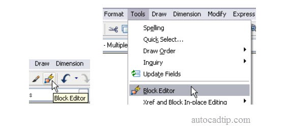
The block editing environment is specifically designed for defining blocks. Make sure that the BLOCKEDITLOCK system variable is set to 0. You can access the Block Editor using any of the following methods:
- BEDIT command
- BE command alias
- Standard toolbar
- Tools menu
- Right-click menu with a block selected
- Block Definition dialog box
Open block editor
Add Parameters and Actions to Block Definitions
In the Block Editor, you can use typical AutoCAD drawing and editing functionality to create and modify the geometry for your block definition. In addition, the Block Editor includes a toolbar and a block authoring palette, which enable you to apply parameters and actions to your block geometry.
The block authoring palette includes three tabs. The first tab contains all of the available parameters. The second tab contains all of the available actions. And the third tab contains sets of the most commonly used combinations of parameters and actions.
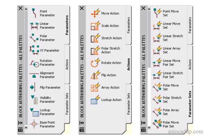
All palettes dynamic block
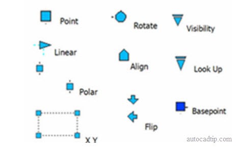
Parameters and actions work together to provide the editing capability of Dynamic Blocks. Parameters are dimensions that drive the block geometry. They are objects with their own relevant properties, which you can edit using the Properties window. For example, you can create a linear parameter to drive the width of a door and then apply properties that constrain the door width to 2-inch increments between the values of 18 and 36 inches. Actions are what change the geometry as you edit a block instance. For example, if you want to change the width of an inserted door block, you must apply a stretch action to the linear parameter that defines the door width. Each parameter only works with specific types of actions, and a few parameters require no actions. We’ll begin with the most basic parameters, the ones that don’t require any actions: Alignment, Visibility and Base Point. These parameters are easy to create and they can dramatically increase the efficiency of your existing blocks with minimal effort. Alignment parameters require no actions although they can be included in the selection set of an action. You can add an alignment parameter to enable a block to align automatically to nearby geometry. If you create the alignment parameter at the origin point of the block, the alignment functionality will be available upon insertion. If you do not add an alignment parameter at the origin point, the alignment capability is available through cycling before you place it or after if you select the alignment grip on an inserted block.
For some blocks, you might find it useful to include multiple insertion points. For example, when inserting a stove block, you might want to insert it using the left corner, the right corner, or the center, depending on the other geometry in the drawing. You can define your blocks with multiple alignment parameters and then use the CTRL key to cycle between the alignment grips upon insertion.
The parameter grips are actual objects in the Block Editor. If you don’t want a grip to be included in the cycling options, you can select the grip in the Block Editor and then use the Properties window to turn off the Cycling option. If you want to change the location of the alignment grips, you can move the grip in the Block Editor. For example, if you want the stove to insert a slight distance away from the wall, you would create or move the alignment grip so that it is away from the stove geometry. In this example, changing the location of the left alignment grip means that it is no longer located at the origin point of the block. Of course, you could move all of the geometry so that it is in the correct relation to the origin. However, the simpler option is to insert a base point parameter.
The base point parameter defines a base point for the Dynamic Block reference relative to the geometry in the block, overriding the default origin point of the block. Like the alignment parameter, the base point parameter does not require any actions, but can belong to an action’s selection set. The base point parameter displays in the Block Editor as a circle with crosshairs.
You can use the visibility parameter to define a block that turns geometry on or off depending on the state. A visibility parameter must include at least two states and you can use the visibility tools in the upper right corner of the Block Editor to switch between states and to show or hide the geometry for each state. For example, a valve block might include five visibility states. The block definition contains the geometry for all of the states but the visibility of the geometry varies between each of the states.
You can combine multiple types of parameters to create a more powerful block definition. For example, you might create a sink block with a visibility parameter to turn on different nested blocks for the plan, front and side views. In addition, you could include alignment parameters at the appropriate locations in each of the three visibility states.
How Do I Know Which Actions Can Be Associated to Parameters?
The following matrix table is a quick reference you can use to determine the appropriate action for each parameter. If you work the matrix backwards by determining the action you want first, then you’ll be able to attach the appropriate parameter. After you determine which combination of parameters and actions will enable you to edit each individual object to meet your needs, you can begin adding the parameters. The process for adding parameters varies depending on the type of parameter.
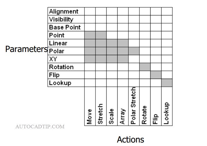
Associate parameters and actions
After you add the parameter, you may see an exclamation point indicating that the parameter requires an action. You can either select an appropriate action from the block authoring tools, or you can double-click on the parameter and select from the list of actions that are available for that parameter. For each action that you add, you will select the specific object(s) that you want that action to edit.
You can continue to add parameters and actions to make your blocks more powerful. In the door example, you might want to add a base point parameter and a flip parameter and action. Using the Properties window, you can apply various properties to the actions, parameters and parameter grips. For example, you might want to change the names of the parameters and actions to something more meaningful.