You can add alignment parameter to dynamic block. Alignment parameter define grips that align the block reference to other geometry in your drawing. Alignment parameter does not define custom properties, cannot have associated actions, and always act on the entire block reference rather than on objects within the block.
When adding an alignment parameter to a block definition, you must define an alignment axis and alignment type (perpendicular or tangent). When moving a dynamic block using an alignment grip and the grip passes over other geometry in the block, AutoCAD rotates the entire block about the grip so that the alignment axis is tangent to the geometry under the grip. (The grip itself will appear tangent or perpendicular to the geometry depending on the setting for the parameter). The alignment grip also snaps to the nearest point on the underlying geometry.
Dynamic block can have multiple insertion points, which you can cycle through by pressing the CTRL key when inserting the block reference. All dynamic block grips have a Cycling property. When this property is set to “Yes”, it can act as an insertion point for the block and can be cycled to while inserting the block.
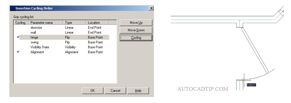
You can modify the Cycling property for a grip by selecting the grip and modifying the property through the Properties palette. You can also modify the cycling properties and change the order in which you activate them on each press of the CTRL key or by invoking the BCYCLEORDER command to display the Insertion Cycling Order dialog.
A door block might define several grips which can be used to automatically align it with other geometry in the drawing, such as walls you place the door in. In this example the block includes an alignment grip at the end of the arc segment to align the block with walls in the drawing.

