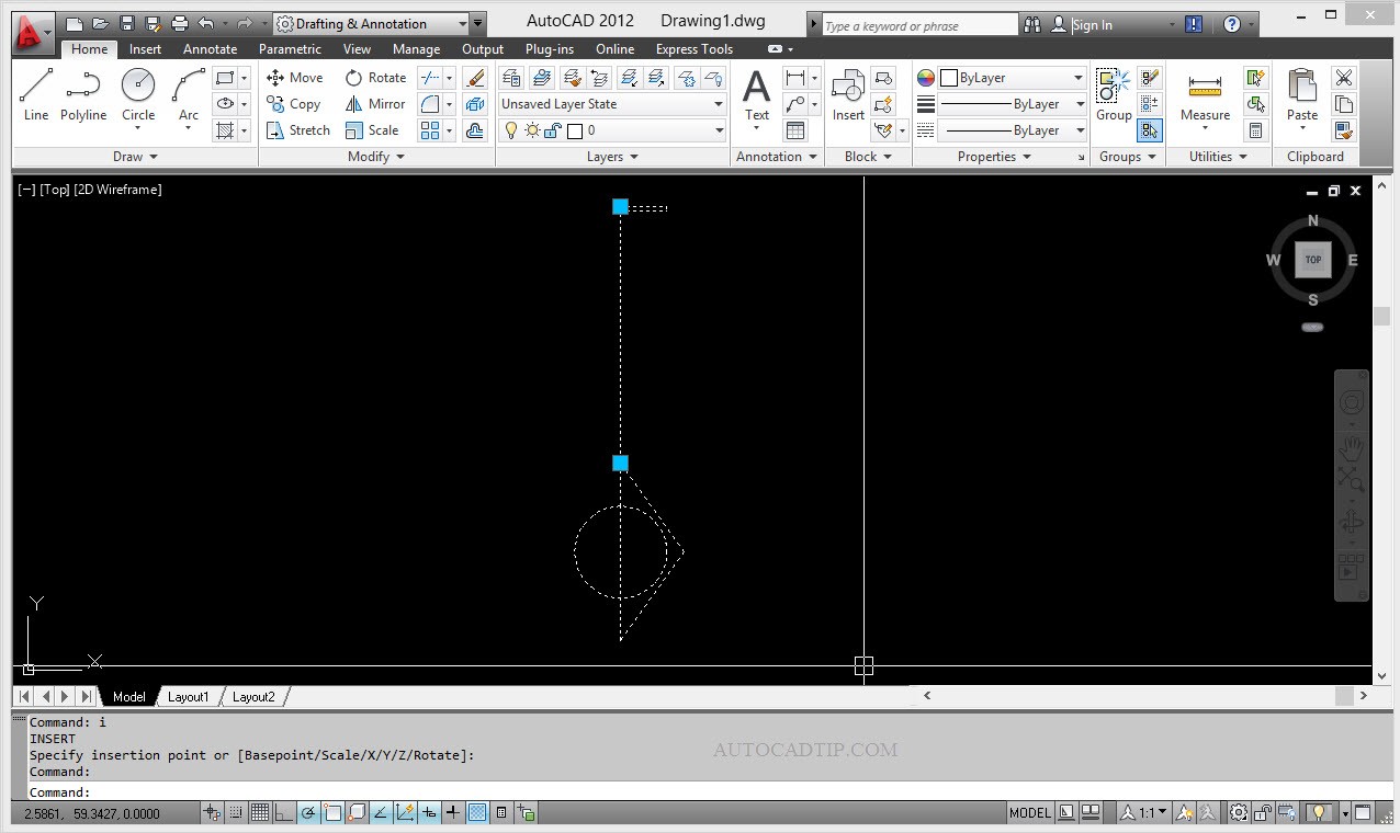
Continuously with dynamic block tutorial. In this series, you will be introduced How to use Polar Stretch action dynamic block AutoCAD.
You create geometry that rotates while it stretches or moves using polar parameter and polar stretch action.
Polar parameter define two custom properties measuring the distance and angle between the two points of the parameter. One of these points (the first one you define when placing the parameter) is called the base point; the other is called the endpoint. When you change the distance property of a Polar Parameter, the base point remains fixed while the endpoint adjusts so that the distance between the two points equals the new distance value. When you change the angle property of a polar parameter the distance between the points remains the same, but the angle formed by the line connecting the points and the block’s axis changes to become the new angle.
Polar stretch action combine the effects of a stretch action with those of a rotate action. Like a stretch action, a polar stretch action is associated with the movement of either the start point or the endpoint of the parameter with which the action is associated. When you define a polar stretch action you must also define the stretch frame and the objects in the block that the action acts upon. You can also define a separate set of objects that are rotated but never stretched.
Similar to the STRETCH command, a stretch action moves objects completely within the stretch frame, while stretching those which cross the stretch frame. However, because polar parameter has angle properties, objects in the polar stretch action’s selection set also rotate as the associated parameter angle changes. The base point of rotation is always the opposite endpoint of the parameter.
The following steps to add Polar Sketch action dynamic block AutoCAD:
Step 1: Make an object
Step 2: Define Block
Step 3: Add Polar Stretch Action to definition block
- Opening block editor interface
- Placing Polar parameter
- Adding Polar Stretch action

