When you show a drawing with layout space, you can use viewport in this environment. Today you will introduce how to create and modify viewport. You can create a single layout viewport so that fits the entire layout or create multiple layout viewports in the layout. Once you create the viewports, you can change their size, their properties, and also scale and move them as needed. With MVIEW command in AutoCAD, you have several options for creating one or more layout viewports. You can also useCOPY and ARRAY to create multiple layout viewports.
Create layout viewport
- Create rectangular layout viewport
Types MV > press Enter and then select first corner and second corner of viewport as same you draw a rectangular.
- Create multiple layout viewport
Types MV > press Enter > type 2 or 3 or 4 so that it is suitable for your requirement and then choose two corners of viewport as the prompt.
- Create a the layout viewport from a object
Before creating it you need to make a close object as circle, ellipses or a close polyline. Once type MV > press Enter > choose O > Enter. Now AutoCAD will convert this into viewport and it becomes boundary for this viewport.
- Create a layout viewport by polyline
Types MV > press Enter > select P > press Enter after that you draw a close object > press Enter to end command. AutoCAD will make a viewport from this object.
Modify layout viewport
After you had made a layout viewport, you have three problems that need to modify.
SCALE: Select its boundary > Ctrl + 1 > at row standard scale, you can select ratio suitable requirement.
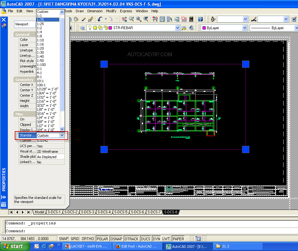
Modify scale of viewport
LOCK: Select its boundary > Ctrl + 1 > at row display lock, you choose YES to lock, so No to unlock.
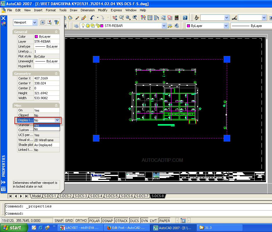
Lock layout viewport
LAYER: Layer viewport’s boundary must be not plot. My advice that you should assign

Assign layer boundary viewport
Video tutorial: